

How to Implement I/O and Object “Load Balancing” & “Redundancy”
SUMMARY
This tech note addresses the concepts of load-balancing and redundancy for both application objects and I/O in a galaxy. I/O in a galaxy is implemented using Device Integration (DI) objects. By using redundancy, you can balance your object load between multiple platforms to use computer resources more effectively.
APPLIES TO:
- Application Server
PROCEDURE
Section 1 – Application Object Redundancy
NOTE: All AOS Platforms should be configured identically, with exception to the “Network address” & “Redundancy Message Channel IP address” Fields.
When configuring redundancy on your own plant network, you will need to discover which network connection you will use before performing these steps.
For the purposes of this tech note, we will be using the following IP addresses:
- AOS1: 10.10.10.101
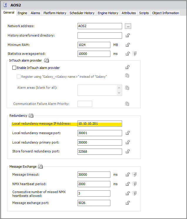
- AOS2: 10.10.10.201
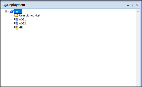
- The first objects you must create are Platforms. A “Platform” simply represents a specific computer. In this document, we will create 3 Platforms – 1 for the GR (Galaxy Repository), 1 for our first AOS (Application Object Server), and 1 for our second AOS. The primary purpose of an AOS platform is to host objects. By having two platforms (AOS servers) that host objects, we can implement failover in our galaxy in addition to load-balancing (the ability to split the object load between multiple servers).
- Two Network Cards are required on each AOS node for redundancy. The following steps cover how to configure a second network connection in Windows, which we will call the Redundancy Message Channel (RMC), which the two AOS nodes will use to communicate with each other.
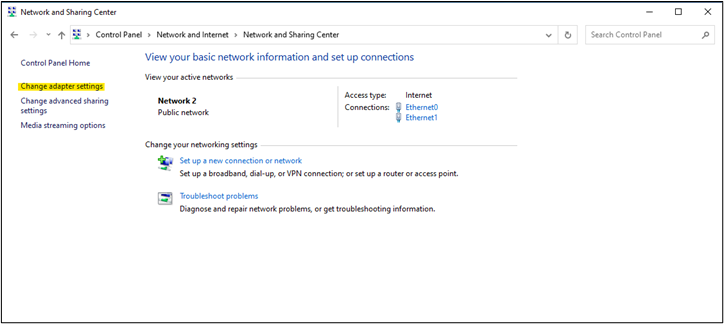
First, on an AOS node, open the Network and Sharing Center (Start | Control Panel | Network and Internet | Network and Sharing Center) and click Change adapter settings.
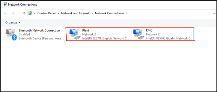
- In the Network Connections window, there should be at least two Network Cards available. One of these network cards will be used to communicate with the GR node and the other will be to communicate with the secondary AOS node. We are going to right-click and rename these to be “Plant” and “RMC” (Redundant Message Channel) respectively.
NOTE: Steps 4-6 will be repeated on both AOS nodes. Step 5 will show screenshots of both AOS1 and AOS2 configurations. Be sure to use the proper IP address depending on which AOS node you are on.
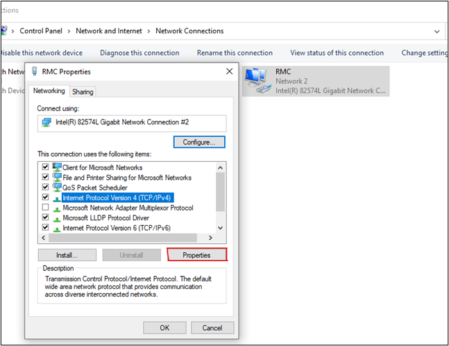
- Right-click RMC, select “Internet Protocol Version 4”, and click Properties.
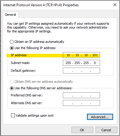
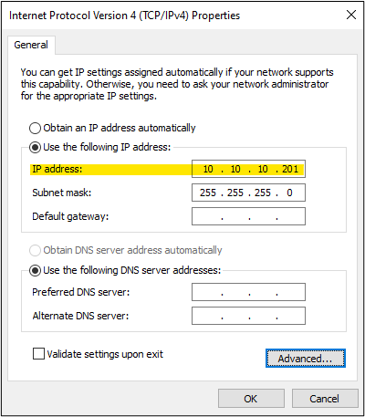
- Choose “Use the following IP Address” and enter the appropriate IP address. As mentioned at the beginning of the tech note, we will be using 10.10.10.101 for AOS1 and 10.10.10.201 for AOS2. We will also be using the default Subnet Mask.
AOS1
AOS2
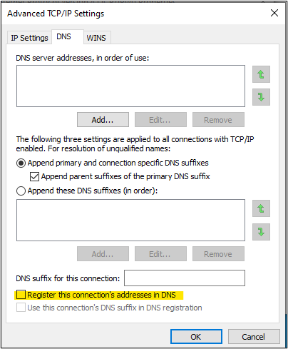
- We will also be unregistering these connection addresses in the DNS, by going to Advanced | DNS and unchecking “Register this connection’s addresses in DNS”.
- Now that we have our RMC network cards configured, we will go back to the GR node in the IDE.
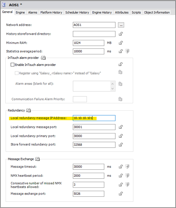
Within the first AOS Platform configuration you will need to enter the RMC (Redundant Message Channel) IP address of that same computer.
Within the second AOS Platform configuration you will need to enter the RMC (Redundant Message Channel) IP address of that same computer.
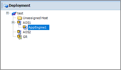
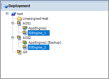
- We will first create our redundant app engines. These engines will host Application Objects, Areas, and Redundant DI objects (RDIOs). We are calling this engine “AppEngine1”. Assign the engine to AOS1.
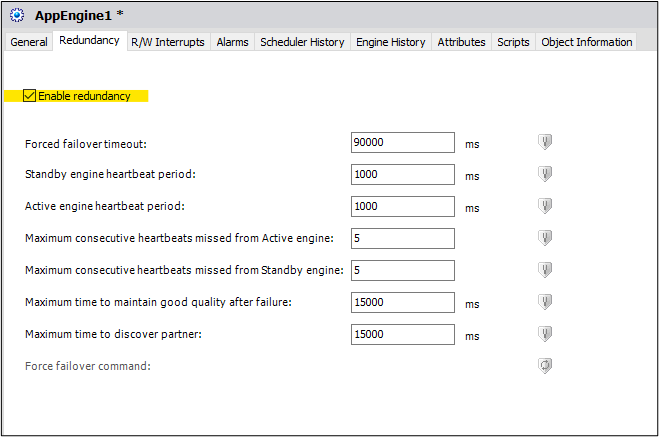
- Open up AppEngine1 configuration and go to the “Redundancy” tab. Check the box to “Enable Redundancy”, and then save + close the object.
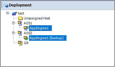
- You should now see a new app engine under Unassigned Host named “AppEngine1 (Backup)”. We are going to assign this to AOS2. These will act as our redundant object engines. If AOS1 were to lose connection for any reason, all the objects from AppEngine1 would switch to running on AppEngine1 (Backup) on AOS2.
Section 2 – Device Integration Redundancy
- Now, create two stand-alone app engines, one for each AOS node. These will be used for the DI (Device Integration) Objects. You should not place any DI Object, other than the RDIO (Redundant DI Object), under a redundant engine; they should each run on their own separate engine. We will name them “IOEngine_1” and “IOEngine_2” respectively.
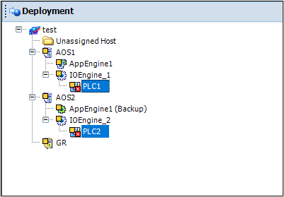
- Under the new engines we will place our DI Objects. For every unique DI Object that exists under AOS_01 or AOS_02, there should be a duplicate on the other server. For this document, we will be using the $DDESuiteLinkClient DI objects and naming them “PLC1” and “PLC2” respectively.
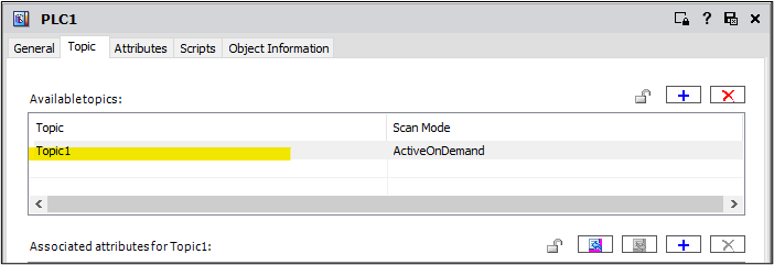
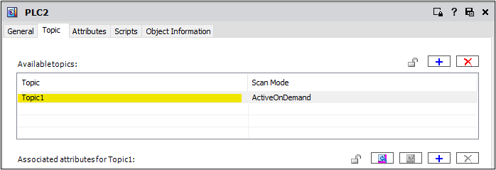
- Below is an image from the “Topic” tab of each DI Object. The topic names should match up exactly for the purpose of the RDIOs.
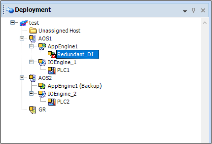
- With two DI Objects created, we can now create a $RedundantDIObject (RDIO) instance. We will call this “Redundant_DI” and host it on AppEngine1.
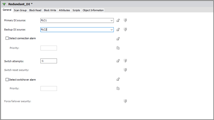
- In the Redundant_DI configuration editor, for the Primary DI Source, we will use PLC1. For the Backup DI Source, we will use PLC2.
- Go to the Scan Group tab. We want to create a common Scan Group (aka Device Group or Topic). To simplify this, we can click the “Copy Common Scan Groups” button.
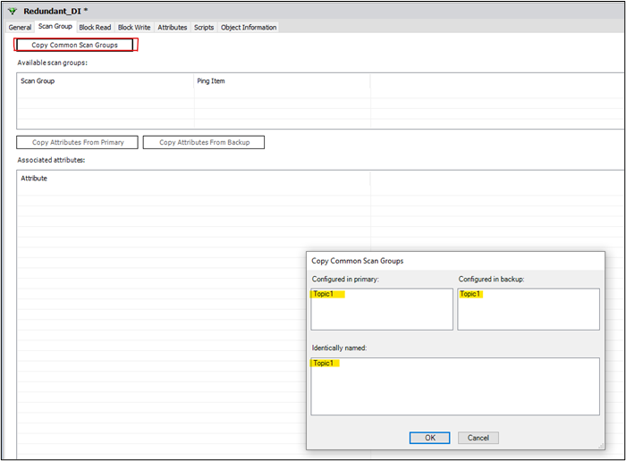
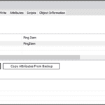
Click OK. In the Available Scan Groups area, “Topic1” appears. You will also want to configure a Ping Item that will be user to monitor the connection to your PLC. This ideally should be an item directly from your PLC. If a Ping Item is not specified, the RDIO will randomly select an item which can result in unexpected behavior.
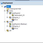
- Below is a snapshot of what the result of our example should look like. Using this concept, you can create redundancy and load balancing for both the Application Objects and the I/O.
All Industrial Software Solutions Tech Notes are provided "as is" without warranty of any kind.